|
|
Graphic Division
|
Graphic division
The experience and production capacity of Vuototecnica has originated a division specially dedicated to the graphics and printing sector. A reference entity, ranging from engineering to services, that offers innovative and advantageous technical solutions under every point of view: performance, reliability, duration and operational economy. A significant demonstration of the Graphic Division specialisation is represented by the new range of products among which:
PNEUMATIC SUCTION AND BLOWING PUMPS
This new generation of highly versatile multiple-ejector pumps (multi-stage) are able to suction or blow as needed and represent a real evolution compared to conventional rotary vane pumps. Characterised by their new generation of ejectors, these pumps boast an excellent ratio between the quantity of air consumed and that suctioned (or generated), benefiting operational consumption. Their level of vacuum (or pressure level) and flow rate can be adjusted based simply on the air supply pressure. The state of the art hi-tech materials have considerably reduced the weight allowing them to be installed directly on the machine. The Vuototecnica research centre has focused its attention on noise reduction, with solutions that provide for full soundproofing and no moving parts, thus prolonging duration and eliminating any vibrations. Furthermore, these pumps are based on the Venturi principle which exploits the compressed air kinetic energy via in-line ejectors and, therefore, do not develop heat. The excellent filtration of the compressed air supply and intake air allows the intake of air free from oil, water condensates and impurities from between the sheets of paper to be separated in the working environment, with no pollution. Other assets of this safe and competitive technology include a minimal maintenance, limited to a regular filter cleaning operation, and reliability with no comparison. The pneumatic suction and blowing pumps are described in the following pages.
VACUUM CYLINDERS
By assembling a vacuum cup onto their perforated stem and creating a vacuum, the cup will quickly come into contact with the sheet or the object to be handled and it will automatically lift it, holding it until the vacuum is excluded. Thanks to all these features, this range of cylinders combined with cups are particularly recommended for separating sheets of paper or plastic. Advantages include: high speed operation, automatic compensation of the height of the objects to be lifted, non-rotating stems and extremely easy fixing. These vacuum cylinders are illustrated and described on the following pages.
VACUUM CUPS
These come in a large variety of shapes and sizes, to guarantee a quick and safe grip and they can be provided in anti-abrasion natural para rubber, nitrile or oil-resistant rubber, silicone, FKM, polyurethane and other compounds, according to the requirements.Vacuum cups are described in detail in Chapter 1. This chapter on the other hand will focus on disc cups only.
|
|
|


|
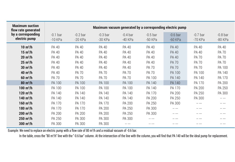
Tables for pneumatic pumps and blowing pump selection
-
|
|
|
|
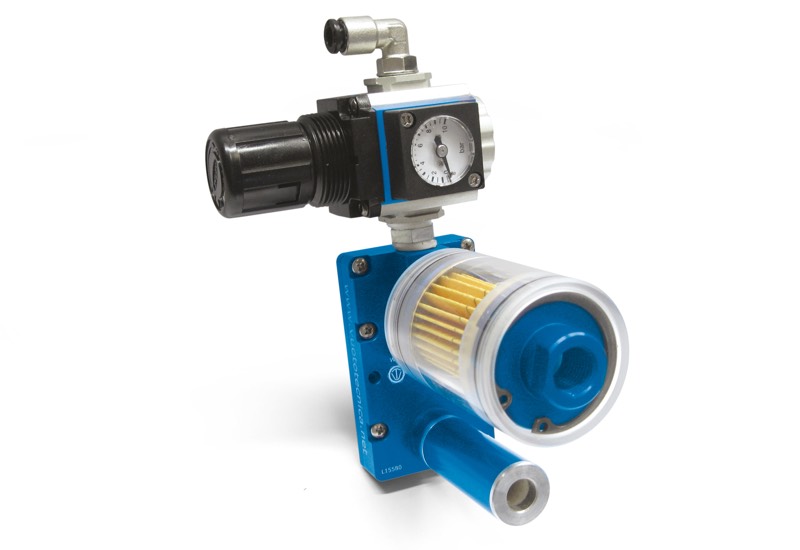
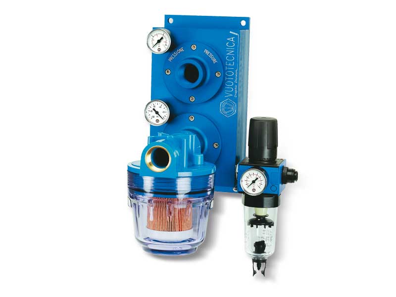
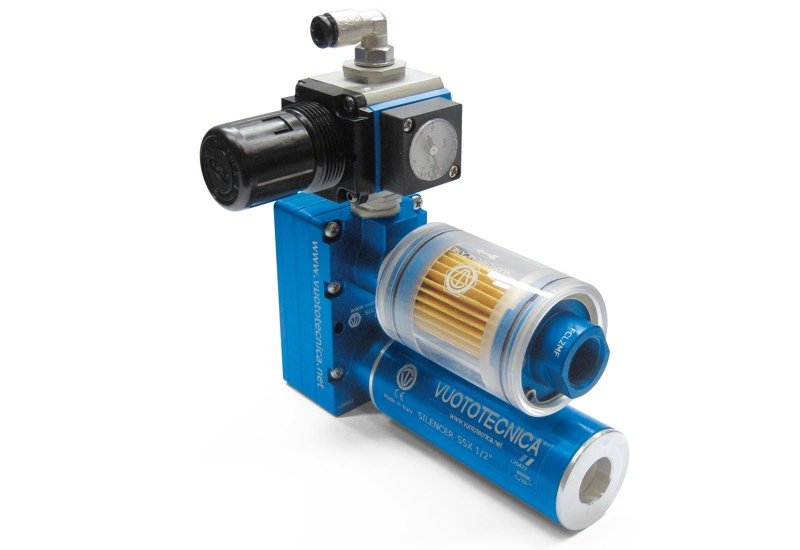
Small pneumatic suction pumps PA
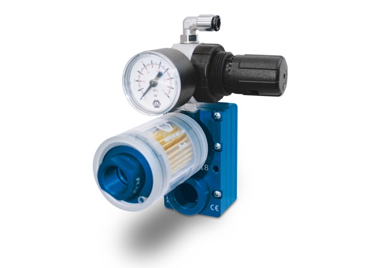
The assembly of a pressure adjuster equipped with pressure gauge and of an FCL filter on the suction inlet connection of a vacuum generator of the M .. SSX range has allowed creating these small pneumatic suction pumps. Their main features include reduced overall dimensions compared to their technical performance.
The level of vacuum and flow rate can be adjusted according to the supply air pressure.
These pumps are powered with compressed air with a pressure ranging from 1 to 5 bar and they can produce a maximum vacuum of 85% and a suction flow rate between 2 and 18 m3/h, measured at a normal atmospheric pressure of 1013 mbar.
Based on the Venturi principle, they do not develop heat.
An SSX silencer screwed onto the pump exhaust ensures a silent operation. The filter equipped with a microporous cartridge is located on the suction inlet connection and can keep the finest dust and impurities.
Thanks to their static operating principle, maintenance is reduced to only a simple regular cleaning of the filter.
Product codes: PA3 PA7
|
|
|
|
Small pneumatic suction pumps PA 10, PA 14 and PA 18
Product codes: PA10 PA14 PA18
|
|
|
|
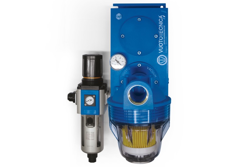
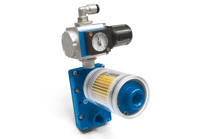
Pneumatic suction pumps PA
A state of the art range of ejectors has allowed creating this range of pneumatic suction pumps featuring an excellent ratio between the amount of consumed air and sucked air, as well as the ability to adjust the vacuum level and capacity according to the supply air pressure.
These pumps are supplied by compressed air with a pressure ranging from 1 to 6 bar (g), and they can produce a maximum vacuum of 90% and a suction capacity between 15 and 320 cum/h, measured at a normal atmospheric pressure of 1013 mbar.
When designing these pumps our attention was focused on noise. In fact, they are perfectly soundproofed and there are no moving parts subject to wear and vibrations. All this results in an extremely silent operation.
Moreover, being based on the Venturi principle, they do not develop heat.
As a standard, they are equipped with a filter/pressure reducer unit for the supply air and a filter with microporous cartridge located on the suction inlet connection which can keep the finest dust and impurities.
The excellent compressed air and sucked filtration allows blowing air free from oil vapours, water condensation and impurities in the work environment, causing no pollution.
The use of light alloys for making these pumps has allowed a considerable reduction of their weight thus allowing them to be directly installed onto the machine. Thanks to their static operating principle, maintenance is reduced to a simple regular cleaning of the filters.
Product codes: PA40 PA70 PA100
|
|
|
|
Pneumatic suction pumps PA 140, PA 170 and PA 200
Product codes: PA140 PA170 PA200
|
|
|
|
Pneumatic suction pumps PA 250 and PA 300
Product codes: PA250 PA300
|
|
|
|
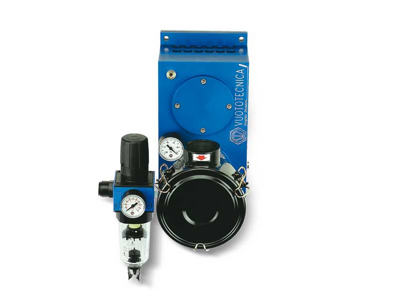
Small pneumatic blowing pumps PS
The assembly of a pressure adjuster equipped with pressure gauge and of an FCL filter on the suction inlet connection of a vacuum generator of the M .. SSX range has allowed creating these small pneumatic suction pumps. Their main features include reduced overall dimensions compared to their technical performance.
The pressure and flow rate can be adjusted according to the supply air pressure.
These pumps are powered with compressed air with a pressure ranging from 1 to 5 bar and can produce a maximum pressure of 0.7 bar and a blowing flow rate between 2.7 and 31 m3/h, measured at a normal atmospheric pressure of 1013 mbar.
Based on the Venturi principle, they do not develop heat.
The filter equipped with microporous cartridge located on the air inlet connection can keep the finest dust and impurities.
Thanks to their static operating principle, maintenance is reduced to only a simple regular cleaning of the filter.
Product codes: PS3 PS7
|
|
|
|
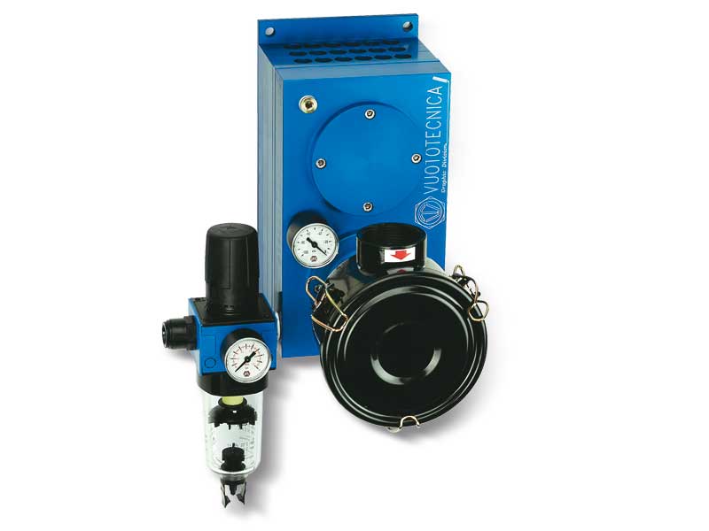
Small pneumatic blowing pumps PS 10, PS 14 and PS 18
Product codes: PS10 PS14 PS18
|
|
|
|
Pneumatic blowing pumps PS
A newly designed range of ejectors has allowed creating this range of pneumatic blowing pumps featuring an excellent ratio between the amount of consumed air and generated air, as well as the ability to adjust the pressure and flow rate according to the supply air pressure.
These pumps are powered with compressed air with a pressure ranging from 1 to 6 bar and have a blowing flow rate between 18 and 425 m3/h, measured at a normal atmospheric pressure of 1013 mbar.
When designing these pumps, our attention was focused on noise. In fact, they are perfectly soundproofed and there are no moving parts subject to wear and vibrations. All this results in an extremely silent operation.
Moreover, as they are based on the Venturi principle, they do not develop heat.
They are equipped as standard with a filter/pressure reducer unit for the supply air and a filter with microporous cartridge located on the air inlet connection which can keep the finest dust and impurities.
The excellent filtration of the compressed air supply and intake air allows the intake of air free from oil, water condensates or impurities from between the sheets of paper to be separated in the working environment, with no pollution.
The use of light alloys for making these pumps has allowed a considerable reduction of their weight thus allowing them to be directly installed onto the machine.
Thanks to their static operating principle, maintenance is reduced to a only a simple regular cleaning of the filters.
Product codes: PS40 PS70 PS100
|
|
|
|
Pneumatic blowing pumps PS 140, PS 170 and PS 200
Product codes: PS140 PS170 PS200
|
|
|
|
Pneumatic blowing pumps PS 250 and PS 300
Product codes: PS250 PS300
|
|
|
|
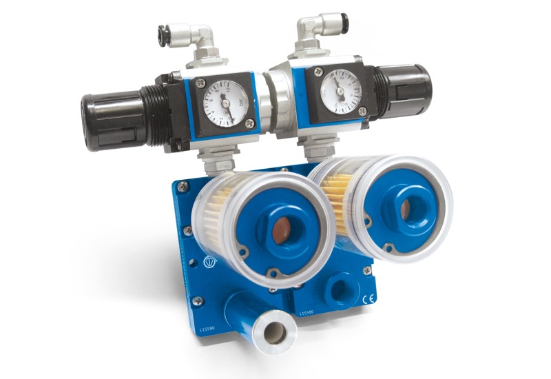
Small combined pneumatic suction pumps PA and blowing pumps PS
All the small pneumatic suction and blowing pumps previously described can be combined regardless of their suction or blowing flow rate.
Given the enormous number of possible combinations, for space reasons, this catalogue only describes combinations of pumps with the same size.
Product codes: PA3PS3 PA3PS7 PA7PS3 PA7PS7
|
|
|
|
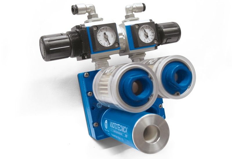
Small combined pneumatic suction pumps PA and blowing pumps PS
Product codes: PA10PS10 PA10PS14 PA10PS18 PA14PS10 PA14PS14 PA14PS18 PA18PS10 PA18PS14 PA18PS18
|
|
|
|
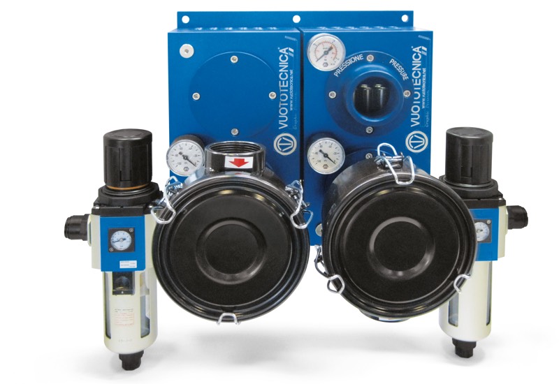
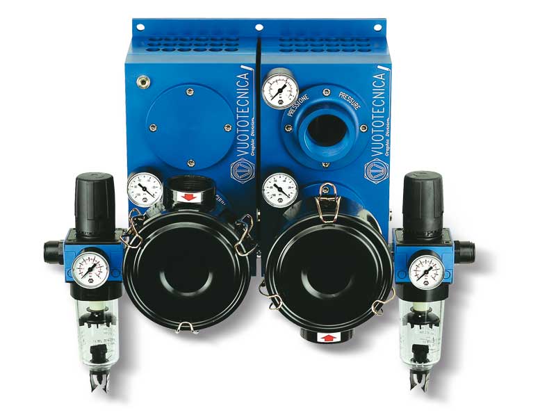
Combined pneumatic suction pumps PA and blowing pumps PS
All the pneumatic suction and blowing pumps previously described can be combined regardless of their suction or blowing flow rate.Given the enormous number of possible combinations, for space reasons, this catalogue only describes combinations of pumps with the same size.
Product codes: PA40PS40 PA40PS70 PA40PS100 PA70PS40 PA70PS70 PA70PS100 PA100PS40 PA100PS70 PA100PS100
|
|
|
|
Combined pneumatic suction pumps PA and blowing pumps PS
Product codes: PA140PS140 PA140PS170 PA140PS200 PA170PS140 PA170PS170 PA140PS200 PA200PS140 PA200PS170 PA200PS200
|
|
|
|
Combined pneumatic suction pumps PA and blowing pumps PS
Product codes: PA250PS250 PA250PS300 PA300PS250 PA300PS300
|
|
|
|
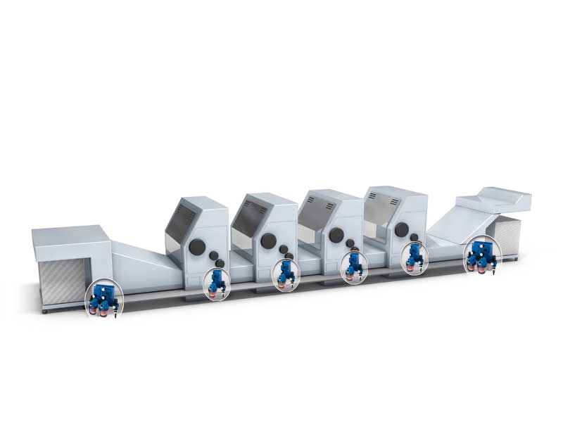
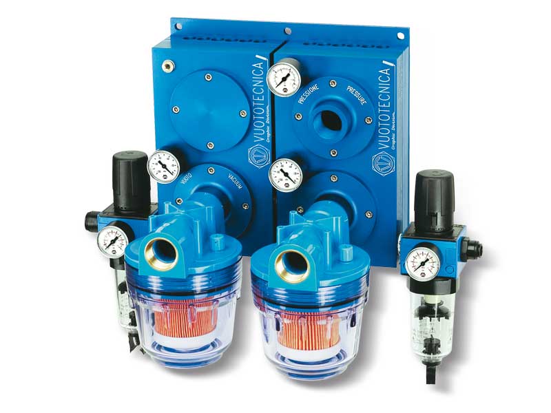
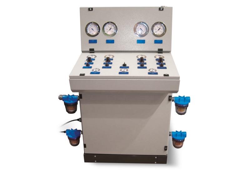
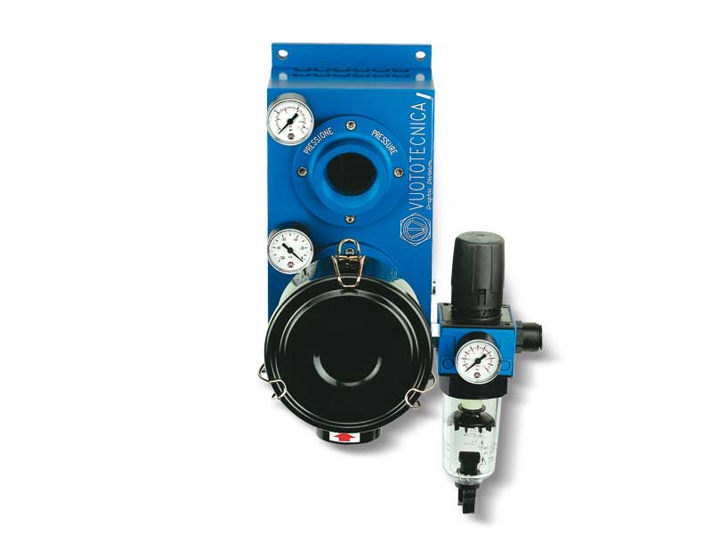
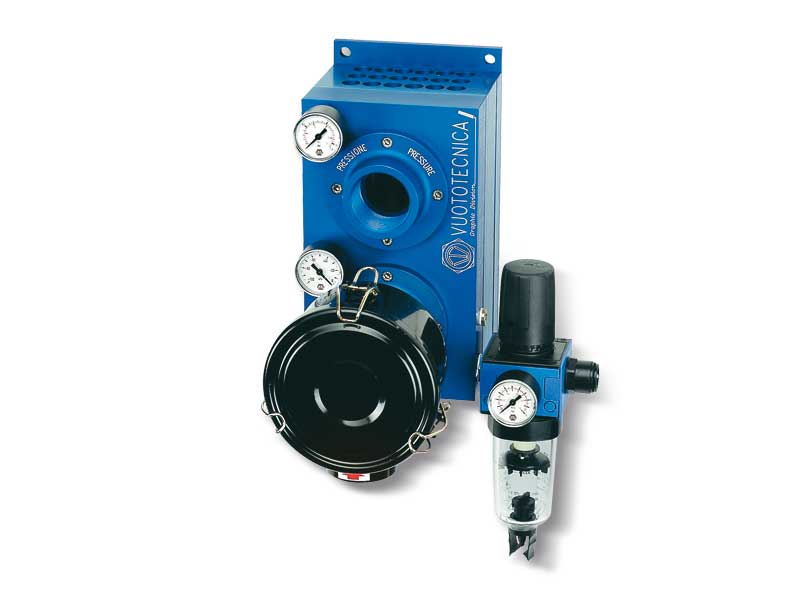
Suction and blowing system AS
With the suction and blowing system AS, we have tried to provide the printing industry with an answer to most of their requirements regarding the management of paper during the printing process, or rather:
- The concentration of all the necessary pumps and commands on one single piece.
- An increased printing quality thanks to individually controlled pumps.
- An increase of productivity resulting from the configuration and use of individual pumps.
- Reduced machine idle state due to the pneumatic pumps based on the Venturi principle.
- An improvement of the work environment thanks to the noise reduction, absence of heat and the emission of air free of oil vapours, water condensation and impurities between the sheets of paper to be separated and in the work environment.
- Energy saving due to a low compressed air consumption compared to the amount of sucked (or generated) air.
- Maintenance reduced to a regular cleaning of the filters.
The suction and blowing system AS is composed of a metal, easy-to-place cabinet, inside of which the combined pneumatic pumps PA and PS are located with the supply compressed air interception and adjustment valves.
The suction and blowing capacities of the pumps are determined according to the client’s requirements or to technical specifications of the machine manufacturer.
The blowing and suction connectors are located on the sides of the cabinet for the connection to the application, as well as the filters equipped with micro-porous cartridge against fine dust.
The following are installed on the control panel:
- The pneumatic main switch for supply compressed air interception with a pressure gauge for a direct reading of the line pressure.- The pneumatic switches for supply compressed air interception of every single pump.
- The pressure reducers with relative pressure gauges for adjusting the compressed air of every single pump. The vacuum (or pressure) level as well as the pump flow rate can be adjusted according to the supply air pressure.
- Vacuum gauges and pressure gauges for a direct reading of the vacuum and pressure at the application. - Vacuum gauges for controlling the clogging level of the PS pump filters.
All our pneumatic suction and blowing pumps can be combined regardless of their suction and blowing flow rate and can be installed inside the system cabinet. Given the enormous number of possible combinations, this catalogue only describes combinations of pumps with the same size.
Product code: AS4
|
|
|
|
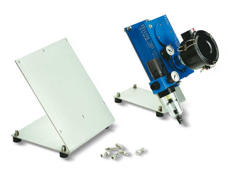
Pneumatic suction and blowing pump holding supports
The supports described on this page have been designed to allow a quick assembly of the pneumatic suction and blowing pumps and their easy placement on the machine.
They are made with a sturdy, satin-finished, stainless sheet steel and are equipped with anti-slip and anti-vibration rubber feet.
These supports are currently available for single pneumatic pumps and for the combined ones.
Product codes: GRDIV03 GRDIV01 GRDIV02
|
|
|
|
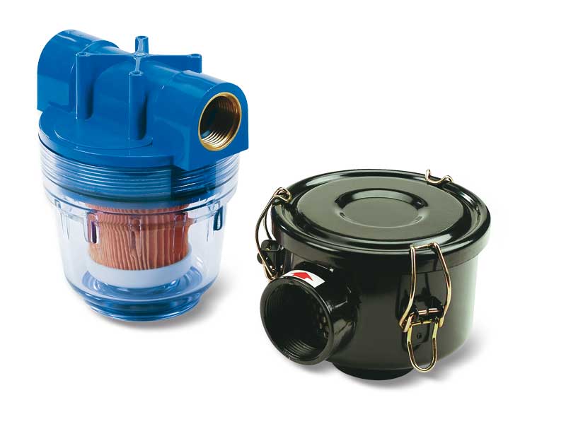
Pneumatic suction and blowing pump suction filters
To allow the pneumatic suction and blowing pumps to work even in very dusty environments, it is necessary to use these filters that, installed on the suction inlet connection, can keep the finest dust and impurities and affecting the flow rate in a negligible manner.
The filtering cartridges, in fact, are made with a special treated paper with a porosity level of 5 - 7 micron, and pleated to increase the filtering surface.
FCL filters are composed of a transparent Plexiglass cylindrical body inside of which is located the filtering cartridge locked by two anodised aluminium flanges that are kept in place by Seeger rings, inside of which the threaded connectors and the seals are housed. The filters can be inspected by simply removing one of the two flanges. The container of the filtering element FP is made with plastic and it is screwed onto the blue plastic lid; a gasket located between the two elements ensures a perfect seal.
The container of the filtering element FC, as well as its lid, are made with sheet steel and varnished with a special oxidation-resistant treatment. A seal between the lid and the container ensures a perfect vacuum seal, while the release clamps on the container allow a quick opening of the lid to check or replace the filtering cartridge.
Product codes: FCL1MF FCL2MF FP30/4/SP FC38 FC55
|
|
|
|
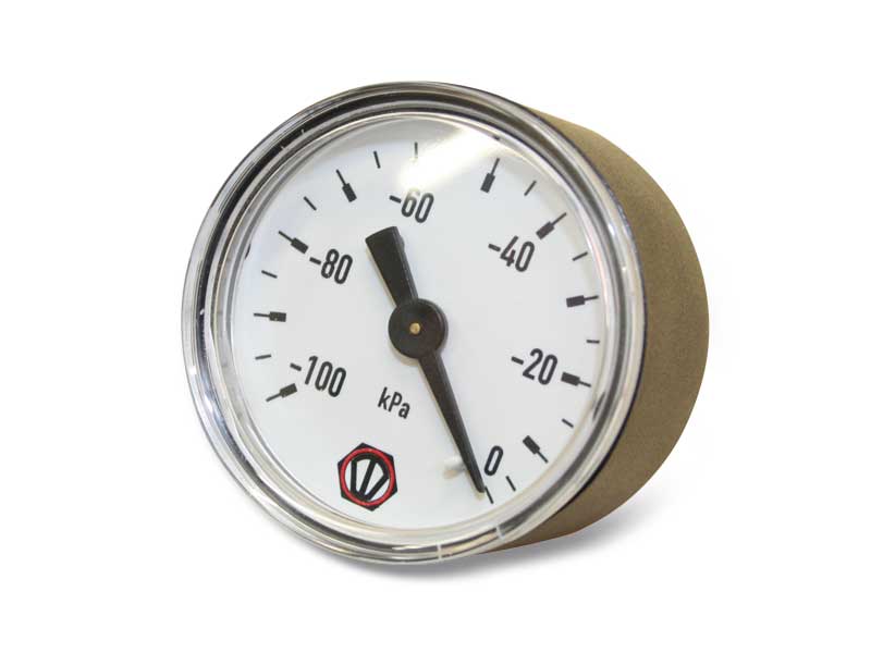
Pneumatic pump spare parts
Vacuum gauge Ø 40 mm with 1/8” coaxial gas coupler
Pressure gauge Ø 40 mm with 1/8” coaxial gas coupler
1/8” gas pressure reducer
1/2” gas filter/pressure reducer
Sealing kit and reed valves
Sealing kit and disc valves
Exhaust silencers SSX
Sound absorbing material on the exhaust
Sound absorbing material on ejectors
Product codes: 090315 090325 090320 FIR00SF FIR03 00KITM3 00KITM7 00KITM10 00KITM14 00KITM18 00KITPVP40M 00KITPVP70M 00KITPVP100M 00KITPVP140M 00KITPVP170M 00KITPVP200M 00KITPVP250M 00KITPVP300M SSX1/4 SSX3/8 SSX1/2 0015110 0015111
|
|
|
|
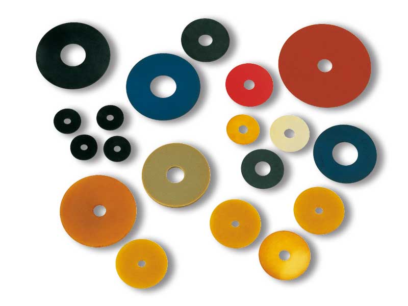
Disc cups
Apart from some standard rubber discs, these items are generally produced upon specific request by the client and for a minimum amount to be specified in the offer phase.
They can be die-cut from sheets or moulded in nitrile rubber, in natural para rubber, silicone or special compounds, as well as in rubberised or polyurethane fabric.
The discs described above are used in the printing industry, as an alternative to vacuum cups, for gripping and handling sheets of paper, cardboard or plastic.
Product codes: 011731N 013041NG 013061N 013091N 015781S
|
|
|
|
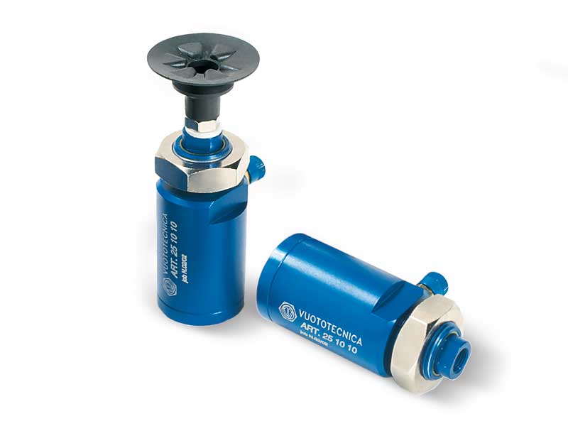
Vacuum cylinders
The cylinders described on this page are vacuum operated.
By creating a vacuum in the anterior chamber of the cylinder, the piston's integrated rod protrudes, overcoming the opposing spring force.
The piston is pushed by the air at atmospheric pressure that gets into the cylinder’s rear chamber through the hollow stem.
The greater the pressure differential between the front chamber under vacuum and the rear chamber at atmospheric pressure, and the larger the piston thrust force will be.
The stem returns into position in two ways:
1) By preventing the atmospheric air from entering through the stem hole and with the vacuum inserted, the pressure differential inside the cylinder is removed. Under this condition, the thrust spring and the atmospheric pressure forces prevail on the stem which is thus pushed into its initial position.
2) By excluding the vacuum, the atmospheric pressure is restored in both the cylinder chambers. Also in this case, being the pressure differential removed, the stem returns to its initial position pushed by the thrust spring.
The first of these two methods is the true operating principle for which this cylinder has been designed. When a vacuum is created, in fact, a vacuum cup mounted on the stem of the perforated cylinder will be brought rapidly into contact with the object to be taken. The object is then automatically lifted and remain gripped during the whole time the vacuum stays engaged.
Because of this feature, vacuum cylinders associated with vacuum cups are recommended for gripping and handling machined, moulded or thermoformed objects, as well as for separating sheets of paper or plastic, sheet steel, etc. and lifting printed circuits or thin plastic panels.
The advantages offered by these vacuum cylinders include: short, fast quick cycles controlled by a single vacuum interception valve, automatic compensation of the height of the objects to be gripped with no compression on them, non-rotating piston and extremely easy fixing.
They are fully made with anodised aluminium and are equipped with a special self-lubricating technopolymer bush which guarantees long duration.
Product codes: 250510 251010 251510
|
|
|
|