|
|
Search results for "bec" Vuototecnica
|
Self-locking vacuum cups with traction release
Their main feature is that they open suction and therefore they produce a vacuum, only when the load to be handled activates the sealing ball.
Especially designed for the vacuum operated beds of woodworking machines, they differ from the previously described ones because of the high precision of their cylindrical support, which is ground to size, and because of their square closing block, which prevents the cup from rotating and enables connection to vacuum.
The cold fitted cups are the flat ones listed in the table, in the various compounds.
The support of these cups is made of anodised aluminium, while the closing block is made of brass.
Product codes: 085040 087540 0810040 0810050 175040 177540 1710040 1710050 086010 088510 176010 178510
|
|
|


|
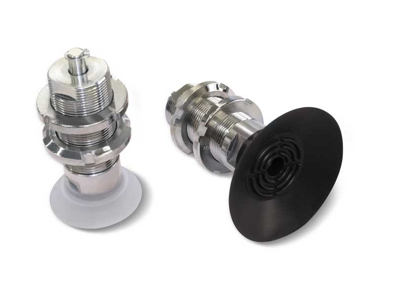
Special built-in vacuum cups with ball valve
Their main feature is that they open suction and therefore they produce a vacuum, only when the load to be handled activates the sealing ball.Especially designed for the vacuum operated beds of woodworking machines, they differ from the previously described ones because of the high precision of their cylindrical support, which is ground to size, and because of their square closing block, which prevents the cup from rotating and enables connection to vacuum.The cold fitted cups are the flat ones listed in the table, in the various compounds.The support of these cups is made of anodised aluminium, while the closing block is made of brass.
Product codes: 016515 056515M 056565 018515 0111010 058515M 0511010M 018515 0111010 058565 0511065
|
|
|
|
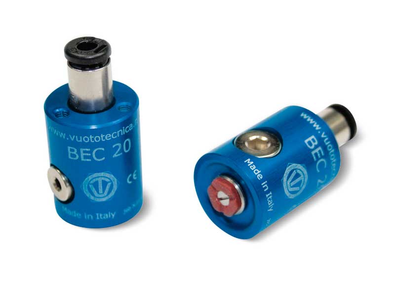
Vacuum cups based on Bernoulli’s theorem
Bernoulli’s theorem explains many phenomena, such as the lifting of a plane’s wing or of a light disc in front of a tube end from which air flows out quickly.
This apparently paradoxical phenomenon is exploited for manufacturing vacuum gripping systems (vacuum cups) and handling, with no contact, fragile objects, such as semiconductor plates, silica discs, solar cells, precious metal foils, films and whatever needs to be handled with the greatest care.
Our cups based on Bernoulli’s principle are made with anodised aluminium, with stainless steel centre thrust disc.
The antistatic silicone spacers, located on the cup gripping plane, prevent transverse movements of the gripped object.
The compressed air supply connections can be axial and radial and the quick coupler for the flexible pipe is included in the package.
The unused holes are closed with brass threaded caps.
On the rear part of the cup there are 3 or 4 threaded holes for fitting it to the automation.
Product codes: BEC20 BEC30 BEC40 BEC60
|
|
|

|
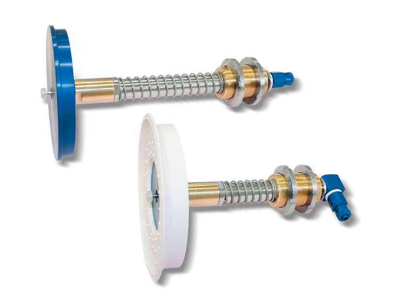
Special vacuum cup holders for bellows cups
They share the same mechanical features at the special vacuum cup holders. The addition of a plunger valve solidly connected to a conical spear valve, which activates suction, and therefore creates vacuum, only when the cup comes into contact with the load to be lifted.
With these cup holders, it is no longer necessary to install cocks on the suction hoses; for this reason, they are recommended in all those cases in which there is a chance that not all the cups come into contact with the load to be lifted (because of an uneven or incomplete load).
The actual springing stroke is:
- For height C= 55 mm 37 mm
- For height C= 110 mm 84 mm
Product codes: 068520 068522 0611020 0611022 0615020
|
|
|
|
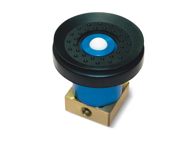
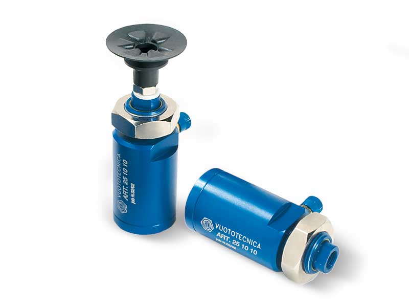
Special vacuum cup holders with push valve
They share the same technical and mechanical features at the special vacuum cup holders. Their distinctive feature is the push valve on the cup support, which activates suction, and therefore creates vacuum, only when the cup is in contact with the load to be lifted.
With these cup holders, it is no longer necessary to install cocks on the suction hoses; for this reason, they are recommended in all those cases in which there is a chance that not all the cups come into contact with the load to be lifted (because of an uneven or incomplete load).
The same push valve can also be applied with no modification to the special articulated cup holders.
The actual springing stroke is:
- For height C= 55 mm 37 mm
- For height C= 110 mm 84 mm
Product codes: 0615022 0620020 0625020 0630020 0635020
|
|
|
|
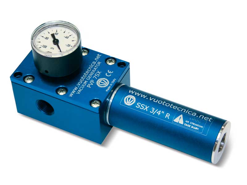
Single-stage vacuum generators PVP 7 SX / SXLP, PVP 14 SX / SXLP and PVP 18 SX / SXLP
Vacuum generators PVP ... SX/SXLP, operate making use of the previously described Venturi principle.
A special new generation silencer installed on them makes them very silent and, thanks to its shape, prevents them from becoming clogged, also allowing the suction of saturated fluids of water condensates or oils, mixed with fine or impalpable powders.
They are supplied as standard with a vacuum gauge for reading the level of vacuum. An additional connection on the body of the generator allows the installation of a vacuum switch for signalling the level of vacuum, or of a pneumatic solenoid valve for a quick restoration of the atmospheric pressure of use. They are fully made with anodised aluminium, with stainless steel ejectors and screws.
These vacuum generators can be used for connecting one or more vacuum cups or equipment with flow rate requirements within the shown values and can operate in particularly dusty or damp environments. Available with suction rates between 8.3 and 18 m3/h and supply pressure 4-6 bar, for items SX and 1-3 bar for items SXLP.
Product codes: PVP7SX PVP14SX PVP18SX PVP7SXLP PVP14SXLP PVP18SXLP
|
|
|
|
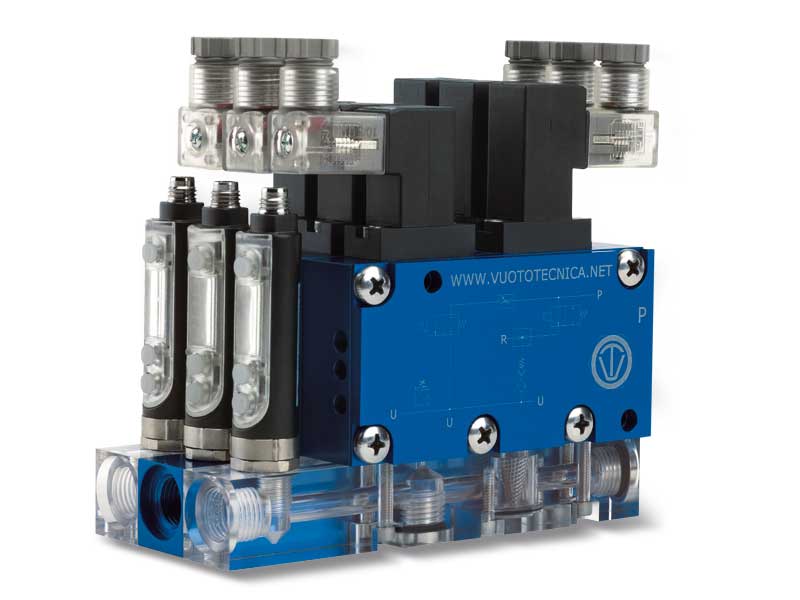
Multi-stage, multi-function and modular intermediate vacuum modules series MI - General description
Intermediate modules are non-independent multi-stage and multi-function vacuum generators to be assembled to the generators of the GVMM range.
Their thickness and weight are reduced to the maximum compared to their suction flow rate and they have been designed to be enclosed between the lid and the base of the GVMM vacuum generator and fixed with screws. The internal connections for the compressed air supply allow communication between them and the basic generator, with no need for external manifolds.
This way, each module becomes an independent vacuum unit that can control an entire vacuum system.
They can be ordered in the desired amount and flow rate, either already assembled onto the GVMM multi-function vacuum generator, or separately, to be assembled to the GVMM generator previously installed onto the machine. In this case, we suggest ordering a screw kit suitable for the number of modules to be assembled.
MI intermediate vacuum modules are made up of the same elements that compose GVMM generators, except for the lid. They operate and they are used as the GVMM multi-function vacuum generator onto which they are assembled.
|
|
|
|
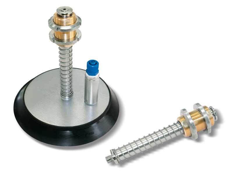
Vacuum cylinders
The cylinders described on this page are vacuum operated.
By creating a vacuum in the anterior chamber of the cylinder, the piston's integrated rod protrudes, overcoming the opposing spring force.
The piston is pushed by the air at atmospheric pressure that gets into the cylinder’s rear chamber through the hollow stem.
The greater the pressure differential between the front chamber under vacuum and the rear chamber at atmospheric pressure, and the larger the piston thrust force will be.
The stem returns into position in two ways:
1) By preventing the atmospheric air from entering through the stem hole and with the vacuum inserted, the pressure differential inside the cylinder is removed. Under this condition, the thrust spring and the atmospheric pressure forces prevail on the stem which is thus pushed into its initial position.
2) By excluding the vacuum, the atmospheric pressure is restored in both the cylinder chambers. Also in this case, being the pressure differential removed, the stem returns to its initial position pushed by the thrust spring.
The first of these two methods is the true operating principle for which this cylinder has been designed. When a vacuum is created, in fact, a vacuum cup mounted on the stem of the perforated cylinder will be brought rapidly into contact with the object to be taken. The object is then automatically lifted and remain gripped during the whole time the vacuum stays engaged.
Because of this feature, vacuum cylinders associated with vacuum cups are recommended for gripping and handling machined, moulded or thermoformed objects, as well as for separating sheets of paper or plastic, sheet steel, etc. and lifting printed circuits or thin plastic panels.
The advantages offered by these vacuum cylinders include: short, fast quick cycles controlled by a single vacuum interception valve, automatic compensation of the height of the objects to be gripped with no compression on them, non-rotating piston and extremely easy fixing.
They are fully made with anodised aluminium and are equipped with a special self-lubricating technopolymer bush which guarantees long duration.
Product codes: 250510 251010 251510
|
|
|
|
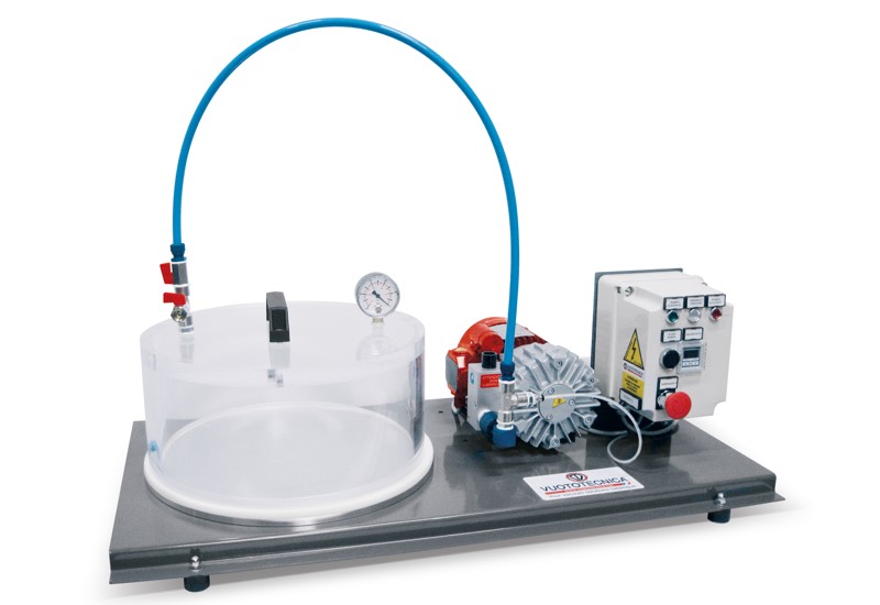
Electrical equipment for vacuum tests
These devices have been created for testing the weldings and, therefore, the sealing of cellophane or PVC wrappings for food products.
In fact, the wrapping placed inside a bell jar tends to inflate because of the pressure differential created between the air at atmospheric pressure contained inside and the vacuum created inside the bell jar. The higher the level of vacuum reached in the bell jar and the greater the thrust that the air contained in the wrapping will exert on the walls and, therefore, on the weldings.
The devices for vacuum tests are composed of:
- A mobile transparent Plexiglass bell jar.
- A support surface with seal.
- A dry rotating vane vacuum pump.
- Two 2-way manual valves for vacuum interception.
- A vacuum gauge for a direct reading of the level of vacuum and the atmospheric air in the bell jar at the end of the cycle.
- A switchgear enclosed in a special protective casing with a digital vacuum switch to adjust the level of vacuum in the bell jar.
- A bent sheet steel frame with anti-vibration feet for assembling all the components described above.
The level of vacuum that can be reached inside the bell jar depends on the pump installed.
The test values are adjustable and can be automatically repeated.
Available in other versions upon request.
Product codes: ATS05 ATS20
|
|
|
|
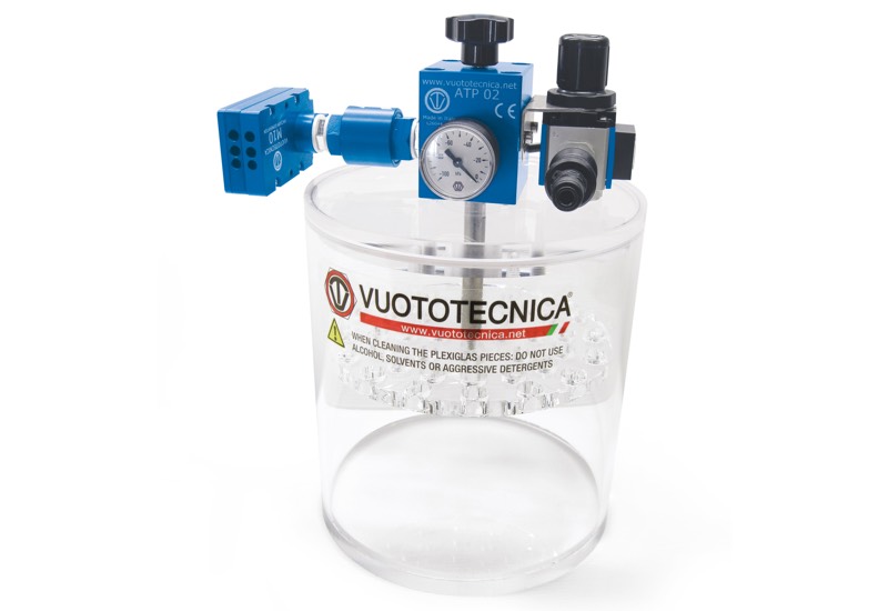
Equipment for vacuum tests
The function of these devices is to test the welding sealing in flow-pack, cellophane or food product wrappings.
They are composed of:
- A transparent Plexiglass cylindrical container into which the water is poured and the vacuum is created.
- A mobile transparent Plexiglass lid with, on its lower part, a perforated disc fixed via a pin which is for keeping the flow-pack wrapping submerged in the water, in the container and on its upper part, the instruments for managing and controlling the vacuum.
- A multiple ejector multi-stage vacuum generator.
- A check valve located on the generator suction inlet to prevent the air from returning into the container when the generator is not in operation.
- A sleeve valve for compressed air interception.
- A supply compressed air reducer equipped with pressure gauge.
- A 2-way manual valve for restoring the atmospheric pressure inside the container.
The wrapping submerged in the water in the container tends to inflate because of the pressure differential produced between the air at atmospheric pressure on its inside and the vacuum created in the container. The higher the level of vacuum reached in the bell jar and the greater the thrust that the air contained in the wrapping will exert on the walls and, therefore, on the weldings. Any air leak from the wrapping due to a defecting welding is proved by bubbles that indicate the exact point of the welding that’s leaking. The level of vacuum that can be reached inside the bell jar depends on the pump installed.
The test values are adjustable and can be automatically repeated.
Available in other versions upon request.
Technical features
Operating pressure: from 0.5 to 1000 absolute mbar
Fluid temperature: from -5 to +50°C
Level of filtration: 60 μ
Product code: ATP02 ATP03 ATP04 ATP07
|
|
|
|